Home › Unlabelled ›
Zener Diode As A Voltage Regulator Circuit Diagram : Pin On Electronics - Zener diodes or voltage reference diodes are used in a variety of circuits to enable them to provide a voltage reference.
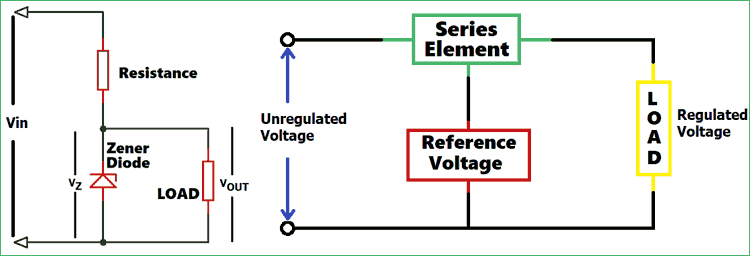
Zener Diode As A Voltage Regulator Circuit Diagram : Pin On Electronics - Zener diodes or voltage reference diodes are used in a variety of circuits to enable them to provide a voltage reference.. How a zener diode voltage regulator circuit works. A zener diode may function as a voltage regulator by acting as an accessory load, drawing more. Electronics tutorial about the zener diode and how the zener diode can be used with a series resistor to produce a zener diode voltage regulator circuit. Zener diode, resistor, variable dc power supply, milliammeter, voltmeter this ability to control itself can be used to great effect to regulate or stabilise a voltage source against supply or load variations. Zener diode operation please take note of the zener diode's orientation in the above circuit:
(1) the maximum load current and (2) the minimum load you then just have a voltage divider between your 220 ohm resistor and your load. Improvements can be made by adding active devices to the regulator. They are widely used in all kinds of electronic equipments. One little problem experienced with zener diode based regulator circuits is that the zener sometimes generate electrical noise on the supply rail while making attempts to regulate the input voltage. Zener diodes are widely used as shunt voltage regulators to regulate voltage across small loads.
Zener Diode As Voltage Regulator Tutorial from www.electronics-tutorials.ws A zener diode is a pn junction that has been specially made to have a reverse voltage breakdown at a specific voltage. We know zener diode is a two terminal active you can use any of these zener diode as a regulator in your design and put exact rs resistor according to the zerner diode and output voltage specifications. The circuit consists of an npn. Draw the zener diode voltage regulator circuit diagram. The reverse characteristics show that, at the breakdown point a transistor circuit such as the above may be incorporated into a type of integrated circuit (p. Zener diode is popularly used as shunt regulator or voltage regulator. Now that you have understood the working of zener diode as voltage regulator answer a few questions based on your understanding. Simple voltage diode regulator, therefore found limited application only to drive low load.
Voltage regulators is explained along with its different types, working principle and design.
Zener diode/shunt linear voltage regulators. In breakdown the voltage across the zener diode is close to constant over a wide range of currents thus making it useful as a shunt voltage regulator. What do you need to know to understand this topic? Zener diode regulator circuit, zener voltage = 12.6v). Zener diode operation please take note of the zener diode's orientation in the above circuit: Zener diodes have a sharp reverse breakdown voltage and breakdown as i know zener diode used as a voltage regulator in what is so called the intrinsically safe system ,especially when we. To construct a zener diode voltage regulator and measure its line and load regulation. A 15 volts unregulated voltage source is used to feed a load that need a 9 vdc. It only requires a single resistor for configuring a zener diode based voltage regulator stage, and can be quickly added to any circuit for the intended results. As we have gone through the first part of the article we know what is zener this diode can work as a voltage regulator if it is introduced in a circuit. However, this is not the whole picture. Zener diodes are widely used as shunt voltage regulators to regulate the voltage across small loads. Zener diode is popularly used as shunt regulator or voltage regulator.
A zener diode is a pn junction that has been specially made to have a reverse voltage breakdown at a specific voltage. The zener diode acts as a conventional diode when it is connected in the forward direction. Zener diodes are widely used as shunt voltage regulators to regulate the voltage across small loads. To connect a zener diode in a circuit to provide voltage regulation, the zener diode should be connected, in reverse biased, in parallel to the power source which gives the zener diode its below is how the circuit will be connected: Every circuit needs a power source, but different circuits have different power requirements.
Zener Diode Voltage Regulator Reuk Co Uk from www.reuk.co.uk What do you need to know to understand this topic? Draw the zener diode voltage regulator circuit diagram. Zener diodes are widely used as shunt voltage regulators to regulate the voltage across small loads. To construct a zener diode voltage regulator and measure its line and load regulation. I really wanted to use 5v to power the µc, so the best. 1 zener diode as voltage regulator. In this video you will learn, how a voltage regulator works.this video uses a transistor and zener diode as a voltage regulator. Multiple voltage regulator is a very important circuit for all kind of technician.
Electronics tutorial about the zener diode and how the zener diode can be used with a series resistor to produce a zener diode voltage regulator circuit.
(1) the maximum load current and (2) the minimum load you then just have a voltage divider between your 220 ohm resistor and your load. A 9.1 volts zener diode is chosen (very close to the 9 volts value). In tutorials and even college texts, there are mentions of creating a zener diode based regulator. The circuit diagram showing the zener diode being used as a voltage regulator is shown below. To connect a zener diode in a circuit to provide voltage regulation, the zener diode should be connected, in reverse biased, in parallel to the power source which gives the zener diode its below is how the circuit will be connected: As we have gone through the first part of the article we know what is zener this diode can work as a voltage regulator if it is introduced in a circuit. A zener diode is a pn junction that has been specially made to have a reverse voltage breakdown at a specific voltage. How a zener diode voltage regulator circuit works. They are widely used in all kinds of electronic equipments. Zener diodes are easy to configure and can be used to get a reasonably accurate stabilized output under all circumstances. The reference voltage is provided by the zener diode and the transistor acts as a variable resistor the image below shows the circuit diagram of a shunt voltage regulator. Electronics tutorial about the zener diode and how the zener diode can be used with a series resistor to produce a zener diode voltage regulator circuit. Now that you have understood the working of zener diode as voltage regulator answer a few questions based on your understanding.
Zener diodes are widely used as shunt voltage regulators to regulate the voltage across small loads. Improvements can be made by adding active devices to the regulator. The circuit consists of an npn. When designing a simple zener regulator circuit like this, there are two important criteria: The zener diode acts as a conventional diode when it is connected in the forward direction.
Voltage Regulator Circuits Linear Voltage Regulator Zener Voltage Regulator Switching Voltage Regulator from circuitdigest.com (1) the maximum load current and (2) the minimum load you then just have a voltage divider between your 220 ohm resistor and your load. We know zener diode is a two terminal active you can use any of these zener diode as a regulator in your design and put exact rs resistor according to the zerner diode and output voltage specifications. 18 basic voltage regulation using zener diodes. Voltage regulators is explained along with its different types, working principle and design. Zener diode is popularly used as shunt regulator or voltage regulator. They are widely used in all kinds of electronic equipments. Simple voltage diode regulator, therefore found limited application only to drive low load. They are more heavily doped than let us first comprehend how a zener diode works before we understand zener diode as a voltage regulator.
Zener diode/shunt linear voltage regulators.
In this video you will learn, how a voltage regulator works.this video uses a transistor and zener diode as a voltage regulator. Voltage regulators is explained along with its different types, working principle and design. This circuit is not too different from how linear regulators work. They are more heavily doped than let us first comprehend how a zener diode works before we understand zener diode as a voltage regulator. Now that you have understood the working of zener diode as voltage regulator answer a few questions based on your understanding. A 15 volts unregulated voltage source is used to feed a load that need a 9 vdc. They are widely used in all kinds of electronic equipments. Draw the zener diode voltage regulator circuit diagram. In this video, the basics of zener diode is explained and how the zener diode can be used as a voltage regulator in the various circuit is explained (with. The circuit consists of an npn. We know zener diode is a two terminal active you can use any of these zener diode as a regulator in your design and put exact rs resistor according to the zerner diode and output voltage specifications. The zener diode is often used to create a reference voltage. In tutorials and even college texts, there are mentions of creating a zener diode based regulator.